Equipment Pad & Site Plan
4000 Chamisa Dr, Austin TX 78730 · v3 — Sep 9, 2026 · companion to the quote request
This page answers one question — how big does the concrete pad need to be — and shows where we propose to put it. It is written for two audiences: the HVAC bidders (confirm or correct the layout in Q-P1 of the quote request) and whoever pours the concrete (the pad and walls may be bid by the HVAC contractor as optional scope line (e), or built by the owner's concrete contractor).
The short answer
| Configuration | Pad size | Area | Notes |
|---|---|---|---|
| Three condensers as quoted now (two Carrier + one Mitsubishi) | 14′-9″ × 5′-11″ → pour 15′ × 6′ | 90 sq ft | Minimum. No room for the future second sound-room unit. |
| Three condensers plus a reserved slot for the future 2nd Mitsubishi (20×20 room) | 20′ × 6′ | 120 sq ft | Recommended minimum. Extra 5′ of concrete now avoids a second pour and a second trench opening later. |
| Above plus pool equipment | L-shape: 20′ × 6′ leg + 6′ × 10′ leg (20′ × 16′ envelope) | 180 sq ft | Pool gear sits along the west wall, north of the condenser row, out of the condensers' service aisle. |
| Same, poured as one rectangle | 20′ × 16′ | 320 sq ft | Simplest to form; the extra 140 sq ft is walkway and future room. Concrete cost difference is small relative to the project. |
Walls (owner's design, an L on the house side and the pool side): long wall ≈ 20′-8″ (along the condenser row, facing the house), short wall ≈ 16′-8″ (along the pool-equipment leg, facing the pool), 8″ thick assumed. The two open sides face the west and north property lines. Height is not fixed yet — at least 12″ above the tallest unit (Carrier top at 47″) so 5′ minimum; 6′ suggested because that is the usual no-permit fence height in Austin (verify) and it blocks line of sight from the yard. Walls sit outside the pad on their own footing with an isolation joint, so the slab stays free to be replaced or extended.
How the dimensions were derived

Row of condensers along the long wall, each unit's back to the wall and service/discharge side facing the open side (west-northwest on site). From the wall corner outward: HP-2 (Carrier 5-ton, the loudest unit, tucked deepest into the corner), HP-1 (Carrier 4-ton), HP-3 (Mitsubishi sound-room unit), reserved HP-4 slot.
| Along the long wall (from the wall corner) | Inches | Why |
|---|---|---|
| Short wall → HP-2 (Carrier 5-ton) | 12 | Carrier minimum to a wall is 6″; 12″ keeps the coil off a hard reflecting surface and leaves room for the lineset loop |
| HP-2 · Carrier 27VNA360 (System 2 — Master Attic) | 35 | Unit is 35″ × 35″ (889 mm square) |
| Gap | 24 | Carrier's multi-unit clearance drawing shows 12″ + 12″ between adjacent units |
| HP-1 · Carrier 27VNA348 (System 1 — Garage Attic) | 35 | Same chassis as the 5-ton |
| Gap | 24 | Also gives the Mitsubishi its 4″ side clearance many times over |
| HP-3 · Mitsubishi PUZ-AK12NL, or SUZ-AA12NL (System 3 — Sound Room) | 34.3 | PUZ is 34-19/64″ W × 11-13/16″ D; SUZ is 31-1/2″ × 11-1/4″ — the slot fits either |
| Gap | 24 | |
| HP-4 slot (System 4, future 2nd sound-room unit) | 36 | Sized for anything up to the 2-ton SUZ/PUZ chassis (33″ × 13″) |
| Far edge | 12 | |
| Row total | 236 → 240 (20′-0″) | Without the future slot: 176 → 15′ |
| Depth (long wall → open side) | Inches | Why |
|---|---|---|
| Wall → Carrier back | 12 | Carrier min 6″. Mitsubishi rear intake needs 4″; we hold 8″. |
| Carrier unit | 35 | |
| Service apron | 24 | Carrier requires 24″ on the service (connection) side. Mitsubishi requires 14″ in front of its discharge; it gets 24″+. |
| Depth total | 71 → 72 (6′-0″) |
Above every unit: Carrier wants 60″ of clear air over the fan — no roof, pergola, or overhang over the pad. Top discharge means the Carrier units are not "aimed"; the Mitsubishi blows horizontally, so it faces the open side.
Equipment on the pad
| Unit | Role | Footprint (W × D) | Height | Weight | Sound (dBA, mfr.) | Min. clearances (mfr.) |
|---|---|---|---|---|---|---|
| HP-2 · Carrier 27VNA360A003 | System 2 — Master Attic, 5-ton | 35″ × 35″ | 47-3/16″ | 369 lb | 58 min / 72 max cooling; 55 / 71 heating | 6″ walls, 12″+12″ between units, 24″ service, 60″ above |
| HP-1 · Carrier 27VNA348A003 | System 1 — Garage Attic, 4-ton | 35″ × 35″ | 47-3/16″ | 348 lb | 56 / 67 cooling; 56 / 68 heating | same |
| HP-3 · Mitsubishi PUZ-AK12NL (primary) | System 3 — Sound Room, 1-ton | 34-19/64″ × 11-13/16″ | 24-13/16″ | 99 lb | 44 cooling / 46 heating | Assumed same as the SUZ drawing (4″ rear, 4″ sides, 14″ front) — bidder to confirm from the PUZ installation manual (Q-P1) |
| HP-3 alternate · Mitsubishi SUZ-AA12NL (only if lineset ≤ 65 ft) | System 3 — Sound Room, 1-ton | 31-1/2″ × 11-1/4″ | 21-5/8″ | 81 lb | 49 cooling / 51 heating | 4″ rear, 4″ sides (8″ one side if only two sides open), 14″ front |
| HP-4 (future) | System 4 — 20×20 room | reserve 36″ × 14″ | — | — | — | — |
Sources: Carrier 27VNA3 Product Data (dimensions page and "Clearances" page), Mitsubishi submittals for PVA-AA12NL/PUZ-AK12NL and SVZ-AP12NL/SUZ-AA12NL, SUZ-AA12NL outdoor dimension drawing. Copies are in specs/submittals/; the full table with every number we rely on is on the equipment data page.
Mounting. Ground pad only — nothing on the house or the sound room. Each unit sits on rubber anti-vibration feet or pads (e.g., 2″ EVA condenser pads or bolt-through isolation feet), then anchored through the feet with stainless wedge anchors at the manufacturer's tie-down points (Carrier: 3/8″ knockouts, 2 places; Mitsubishi SUZ: two 3/8″ × 13/16″ slots at 19-11/16″ bolt pitch; PUZ: per its installation manual — bidder to mark on the plan). Raise the Mitsubishi 3–4″ (its accessory pad or feet) so defrost water drains and the base does not sit in runoff.
Pool equipment allowance
The existing pool equipment (pump, filter, heater, automation) moves into the corral, along the short wall beside the condenser row. It sits on its own pad today, so the concrete contractor measures that pad and sizes this leg from it; the 6′ × 10′ zone on the plan is a placeholder for a typical set. Two notes for whoever lays it out: a gas heater needs its own vent clearances and must not exhaust toward the condensers' intakes, and a heat-pump pool heater is another fan-and-compressor noise source that belongs at the far end from the house. Neither changes the condenser row.
Concrete notes for whoever pours it
- 4″ minimum slab, 3,000 psi, #3 rebar at 18″ each way or 6×6 W1.4 mesh, on 4″ compacted base; thicken to 6″ under the pool heater if it is gas.
- Top of slab 4″ above finished grade; slope 1/8″ per foot toward the open sides, so defrost water and rain drain away from the walls. Level enough that units sit within the manufacturer's tolerance (shim at the isolation feet).
- Walls on their own footing, isolation joint to the slab. Keep the inside face of the long wall exactly 12″ from the Carrier backs (see plan), not closer.
- Sleeves and stub-ups through the slab at each unit position for the lineset chase(s), the control wiring, and the electrical conduit — located by the HVAC contractor before the pour (see quote request Q-P7). Chases arrive under the slab from the trench; nothing runs on top of the slab across the service aisle.
- 811 utility locate before excavation. The pad sits close to the west property line (see below) — confirm the plat's side-yard setback and any utility easement before final placement, and have the line staked.
Where it goes
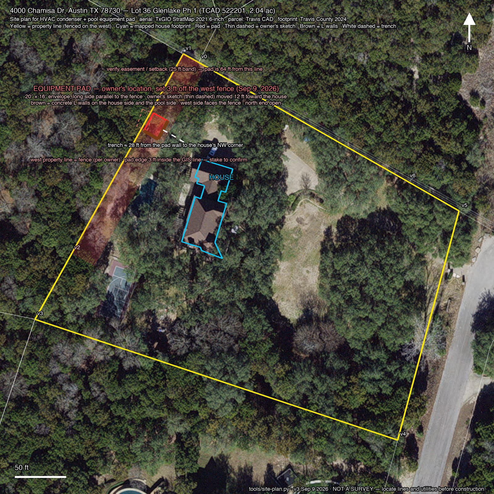
Location set by the owner on Sep 9, 2026. His marked-up satellite view (assets/src/owner-pad-location.jpeg, georeferenced onto the parcel map by tools/georef-owner-mark.py) puts the pad northwest of the house, a few feet off the west property fence. The drawing places the 20′ × 16′ envelope with its long side parallel to that fence line, its outer edge 3 ft inside the appraisal district's line (the fence sits on the line), at the along-fence position of his sketch — which means the envelope sits about 12 ft closer to the house than the sketch's center, because the sketch straddled the GIS line. Close-up: pad detail. Corner coordinates are in assets/site-plan-report.json; pad center ≈ 30.36096° N, 97.84896° W; long axis 29° east of north.
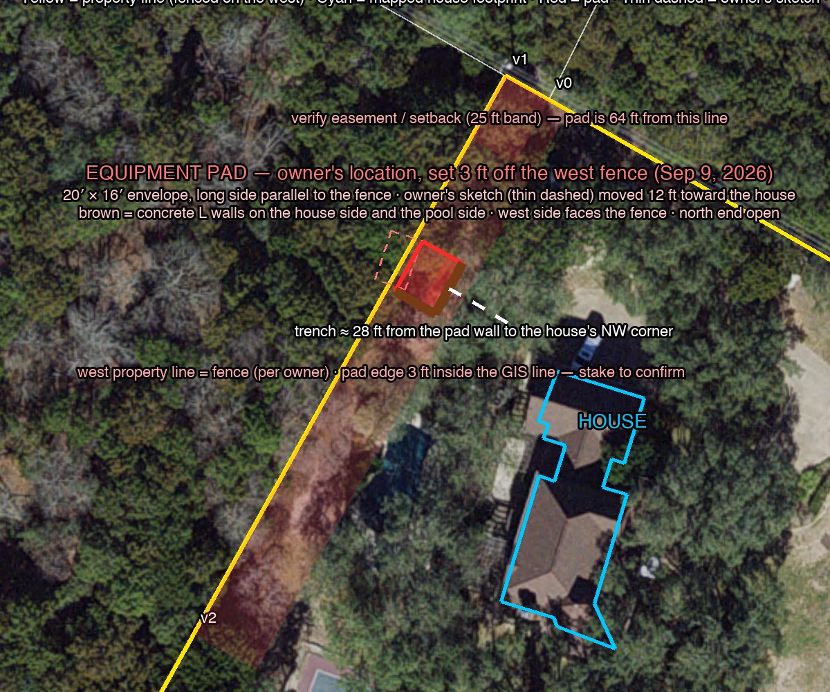
| Measured on the plan | |
|---|---|
| Trench, pad's house-side wall to the house's NW roof corner | ≈ 28 ft |
| Pad edge to the west property line / fence (v1–v2) | 3 ft by design — stake the fence line before forming; if the fence is not exactly on the GIS line, hold 3 ft off the fence |
| Pad edge to the north property lines (v0–v1, v6–v0) | ≈ 64 ft |
| Pool (south of the pad) | short wall faces it |
What faces where. The L walls go on the long side toward the house and on the short south end toward the pool. The west long side — the condensers' service side and the Mitsubishi discharge — faces the fence about 3 ft beyond the pad edge (36″ from the units' service apron, more than Carrier's 24″); the north end is open. Bidders should say if they see a recirculation or access problem with a fence that close (Q-P1, Q-P4).
Why the location matters for equipment selection. Refrigerant lines run from the pad, under the trench (~28 ft), up into the attic (10–15 ft), and across to the air handler: call it 50–80 ft depending on where AHU-3 lands in the attic. The Carrier heat pumps allow 200 ft actual and need the long-line guideline above 80 ft. The Mitsubishi SUZ-AA12NL allows 65 ft total, so it works only if the sound-room air handler sits toward the northwest end of the attic; the P-series PUZ-AK12NL allows 100 ft and is quieter (44/46 vs 49/51 dBA), so the quote request lists PVA-AA12NL + PUZ-AK12NL as primary and the SVZ/SUZ as the alternate if the measured route is 65 ft or less (Q-E6).
Base data: TxGIO StratMap 2021 6-inch orthoimagery; Travis CAD parcel polygon (PROP_ID 522201, Lot 36 Glenlake Ph 1, 2.04 ac); Travis County 2024 building-footprint layer (offset from the actual roof by several feet — the trench distance is measured to the roof corner on the owner's image, not to the footprint); owner's Google Maps mark-up registered to the aerial by overlay matching (±5 ft). Not a survey.
Sequence
- Owner has set the pad location (Sep 9). Still to confirm: wall height; the concrete contractor measures the existing pool-equipment pad for the short leg.
- HVAC contractor marks stub-up positions, chase count/size, conduit count/size on this plan.
- 811 locate → trench, chases and conduits → pad (stub-ups set) → walls → condensers set on isolation feet → linesets, charge, electrical → commissioning.